ASVAB Assembling Objects: Track One Feature at a Time
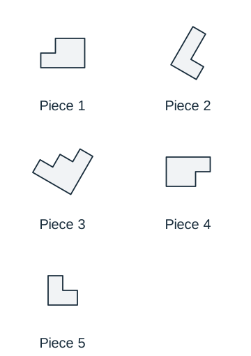
You do not have to imagine a whole assembly at once. Begin with one distinctive feature, preserve its relationship to the rest of the piece and eliminate any arrangement that breaks that relationship.
Test Ninjas Research · Updated September 29, 2026
What you’ll learn
Track a distinctive edge or corner through a rotation.
Distinguish a rotation from a reflected shape.
Check every required piece or connection before choosing.
Learn the method
Tell a rotation from a mirror image
In this warm-up, the original flat piece may rotate in its plane but may not be flipped over. Which candidate, A or B, can be made by rotating it?
A turns the original clockwise by a quarter-turn. B reverses the side on which the short foot attaches.
Choose a feature pair
Find the long upright arm and the short foot at its lower end. Track how the foot attaches, rather than comparing only the overall size.
Turn the whole piece together
A quarter-turn clockwise lays the long arm horizontally, with the short foot pointing downward at the left. That is candidate A. The arm and foot keep their relationship through the turn.
Reject a changed relationship
Candidate B is reflected left to right. Matching its upright arm leaves the foot on the opposite side; rotating to match that foot moves it to the wrong end. Rotation alone cannot make both features agree.
Candidate A is a rotation. Candidate B requires a reflection.
Why the tempting approach fails
Equal area and matching side lengths do not prove that two asymmetric pieces are rotations of one another. Check the order and placement of their features, and follow the movement rules stated in the item.
Explain it back
After one piece appears to match a proposed assembly, what still needs checking?
Compare your reasoning
Every other required piece and connection. One local match can coexist with a missing piece, a duplicated piece or an incorrect join elsewhere in the assembly.
Key concepts to keep handy
The example teaches one method. Open a concept below when you need a rule or a different type of example during practice.
Start with a distinctive feature
Find a long edge, unusual notch or asymmetric corner in the separate pieces. Look for that feature in each proposed assembly. A distinctive feature often eliminates an option faster than imagining every piece moving at once.
Keep rotation separate from reflection
Rotation turns a piece; reflection reverses its handedness. An asymmetric shape can keep the same side lengths yet become a mirror image that rotation alone cannot reproduce. Follow the movement rules of the particular question and preserve the order of features around the piece.
Check the whole assembly after a local match
One matching edge does not establish the answer. Confirm that every required piece is present and that the result does not need a piece to stretch, disappear or duplicate. For flat puzzle items that specify no overlaps, also check for gaps or overlaps. Use those constraints only when the item’s directions require them.
Track labeled connections independently of orientation
In connection-point problems, follow the named endpoints before judging the final outline. Rotating a part changes where its labels appear on the page but not which label belongs to each point. Check every required pairing; an option can look plausible while connecting one point to the wrong partner.
Topics covered in this guide
Recognizing pieces inside a completed figure
Tracking rotation while preserving shape
Comparing edges, corners and notches
Following labeled connection points
Rejecting missing, duplicated or reflected pieces
Now apply what you know
Try a few questions without opening the solutions, then explain why each answer works. Use scratch paper for calculations and work without a calculator. These original, untimed questions sample the subject; the result is not an official score.
Assembling Objects practice: 12 questions
Work through one question at a time. Explain your approach, check the worked answer, then move on. Use scratch paper for calculations.
0 of 12 checked · 0 correct.
Progress is saved in this browser. These original study questions do not produce an official AFQT score.
Question 1: Connection points
Question 1 · Connection points · easy
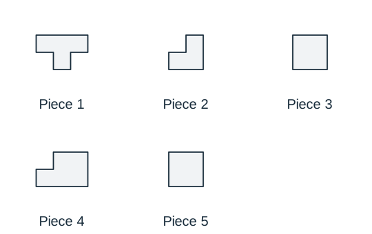
Which diagram joins the pictured objects with the connector by matching A to A and B to B? The objects and connector may be moved and rotated, but must keep their shapes and may not be flipped or resized. Black dots in the choices show the contacts.
Worked answer and explanation
Answer: B. Diagram B
Diagram B joins each object at its original marked location. Follow the unequal neighboring edges around A and B to identify those locations after rotation; preserve the connector’s segment lengths and turns. The other candidates attach at a different location on the A object, the B object, or both. A connector touching two boundaries is not enough: it must touch the specified points.
Question 2: Puzzle assembly
Question 2 · Puzzle assembly · medium
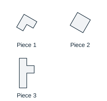
Which diagram can be made using all 3 pictured pieces exactly once? Pieces may be moved and rotated, but not flipped, resized, stretched, or overlapped. Interior lines show the boundaries between pieces.
Worked answer and explanation
Answer: B. Diagram B
Diagram B preserves the boundary of every source piece under movement and rotation. Match the unequal edge lengths and the order of corners around each piece, then trace the shared seams. All 3 pieces fit without overlap. The other alternatives reverse handedness, change edge proportions or curvature, or distort individual pieces; matching only the outside outline is insufficient.
Question 3: Connection points
Question 3 · Connection points · medium
Which diagram joins the pictured objects with the connector by matching A to A and B to B? The objects and connector may be moved and rotated, but must keep their shapes and may not be flipped or resized. Black dots in the choices show the contacts.
Worked answer and explanation
Answer: A. Diagram A
Diagram A joins each object at its original marked location. Follow the unequal neighboring edges around A and B to identify those locations after rotation; preserve the connector’s segment lengths and turns. The other candidates attach at a different location on the A object, the B object, or both. A connector touching two boundaries is not enough: it must touch the specified points.
Question 4: Puzzle assembly
Question 4 · Puzzle assembly · hard
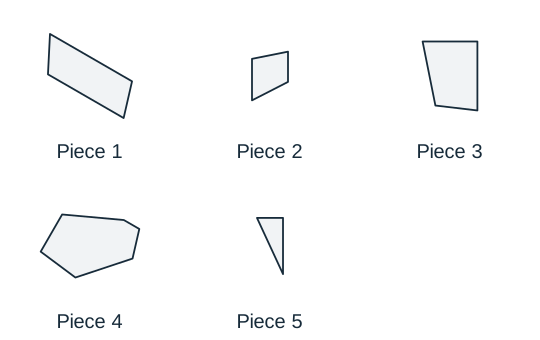
Which diagram can be made using all 5 pictured pieces exactly once? Pieces may be moved and rotated, but not flipped, resized, stretched, or overlapped. Interior lines show the boundaries between pieces.
Worked answer and explanation
Answer: B. Diagram B
Diagram B preserves the boundary of every source piece under movement and rotation. Match the unequal edge lengths and the order of corners around each piece, then trace the shared seams. All 5 pieces fit without overlap. The other alternatives reverse handedness, change edge proportions or curvature, or distort individual pieces; matching only the outside outline is insufficient.
Question 5: Connection points
Question 5 · Connection points · easy
Which diagram joins the pictured objects with the connector by matching A to A and B to B? The objects and connector may be moved and rotated, but must keep their shapes and may not be flipped or resized. Black dots in the choices show the contacts.
Worked answer and explanation
Answer: B. Diagram B
Diagram B joins each object at its original marked location. Follow the unequal neighboring edges around A and B to identify those locations after rotation; preserve the connector’s segment lengths and turns. The other candidates attach at a different location on the A object, the B object, or both. A connector touching two boundaries is not enough: it must touch the specified points.
Question 6: Puzzle assembly
Question 6 · Puzzle assembly · medium
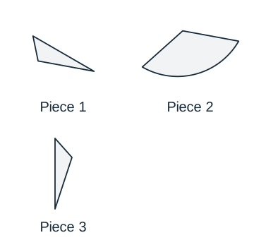
Which diagram can be made using all 3 pictured pieces exactly once? Pieces may be moved and rotated, but not flipped, resized, stretched, or overlapped. Interior lines show the boundaries between pieces.
Worked answer and explanation
Answer: C. Diagram C
Diagram C preserves the boundary of every source piece under movement and rotation. Match the unequal edge lengths and the order of corners and curved edges around each piece, then trace the shared seams. All 3 pieces fit without overlap. The other alternatives reverse handedness, change edge proportions or curvature, or distort individual pieces; matching only the outside outline is insufficient.
Question 7: Connection points
Question 7 · Connection points · medium
Which diagram joins the pictured objects with the connector by matching A to A and B to B? The objects and connector may be moved and rotated, but must keep their shapes and may not be flipped or resized. Black dots in the choices show the contacts.
Worked answer and explanation
Answer: A. Diagram A
Diagram A joins each object at its original marked location. Follow the unequal neighboring edges around A and B and the curved boundary to identify those locations after rotation; preserve the connector’s segment lengths and turns. The other candidates attach at a different location on the A object, the B object, or both. A connector touching two boundaries is not enough: it must touch the specified points.
Question 8: Puzzle assembly
Question 8 · Puzzle assembly · hard
Which diagram can be made using all 5 pictured pieces exactly once? Pieces may be moved and rotated, but not flipped, resized, stretched, or overlapped. Interior lines show the boundaries between pieces.
Worked answer and explanation
Answer: A. Diagram A
Diagram A preserves the boundary of every source piece under movement and rotation. Match the unequal edge lengths and the order of corners around each piece, then trace the shared seams. All 5 pieces fit without overlap. The other alternatives reverse handedness, change edge proportions or curvature, or distort individual pieces; matching only the outside outline is insufficient.
Question 9: Connection points
Question 9 · Connection points · easy
Which diagram joins the pictured objects with the connector by matching A to A and B to B? The objects and connector may be moved and rotated, but must keep their shapes and may not be flipped or resized. Black dots in the choices show the contacts.
Worked answer and explanation
Answer: B. Diagram B
Diagram B joins each object at its original marked location. Follow the unequal neighboring edges around A and B to identify those locations after rotation; preserve the connector’s segment lengths and turns. The other candidates attach at a different location on the A object, the B object, or both. A connector touching two boundaries is not enough: it must touch the specified points.
Question 10: Puzzle assembly
Question 10 · Puzzle assembly · medium
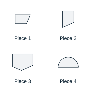
Which diagram can be made using all 4 pictured pieces exactly once? Pieces may be moved and rotated, but not flipped, resized, stretched, or overlapped. Interior lines show the boundaries between pieces.
Worked answer and explanation
Answer: B. Diagram B
Diagram B preserves the boundary of every source piece under movement and rotation. Match the unequal edge lengths and the order of corners and curved edges around each piece, then trace the shared seams. All 4 pieces fit without overlap. The other alternatives reverse handedness, change edge proportions or curvature, or distort individual pieces; matching only the outside outline is insufficient.
Question 11: Connection points
Question 11 · Connection points · medium
Which diagram joins the pictured objects with the connector by matching A to A and B to B? The objects and connector may be moved and rotated, but must keep their shapes and may not be flipped or resized. Black dots in the choices show the contacts.
Worked answer and explanation
Answer: B. Diagram B
Diagram B joins each object at its original marked location. Follow the unequal neighboring edges around A and B and the curved boundary to identify those locations after rotation; preserve the connector’s segment lengths and turns. The other candidates attach at a different location on the A object, the B object, or both. A connector touching two boundaries is not enough: it must touch the specified points.
Question 12: Puzzle assembly
Question 12 · Puzzle assembly · hard
Which diagram can be made using all 5 pictured pieces exactly once? Pieces may be moved and rotated, but not flipped, resized, stretched, or overlapped. Interior lines show the boundaries between pieces.
Worked answer and explanation
Answer: B. Diagram B
Diagram B preserves the boundary of every source piece under movement and rotation. Match the unequal edge lengths and the order of corners around each piece, then trace the shared seams. All 5 pieces fit without overlap. The other alternatives reverse handedness, change edge proportions or curvature, or distort individual pieces; matching only the outside outline is insufficient.
Before moving on, choose one error you can explain. Rework that question with the solution closed, then revisit the skill in a later session to check what you remember.
Common mistakes to check
Accepting a mirror image when the task allows only rotation.
Matching one edge while overlooking a missing or duplicated piece.
Choosing an attractive outer outline without checking internal joins.
Forgetting which marked point belongs to which piece after mentally rotating it.
Compare one constraint at a time
Choose a feature, eliminate options that fail it, and then test a second feature. For connection questions, work through the required pairs in a consistent order. This produces a repeatable method instead of a sequence of visual guesses.
Use explanations to name the error
After checking an answer, identify the decisive mismatch: reflected corner, wrong connection, missing piece or impossible join. Revisit the image and confirm it yourself. The purpose is to improve the comparison method, not memorize the appearance of a particular answer.
Test format and scoring reference
Assembling Objects measures spatial ability and is outside the AFQT. Its score is used in relevant service composites. A short visual practice set is useful for learning the task but does not produce an official spatial standard score.
View Assembling Objects questions and time limits
Assembling Objects: official test format
Format
Questions and timing
Computer test, without tryouts
15 scored questions · 18 minutes without tryouts
Computer test, with tryouts
15 possible additional unscored questions · 38 minutes total with tryouts
Paper test
25 questions · 15 minutes
Domain
Spatial
Contributes to the AFQT
No
The computer test includes unscored tryout questions in selected subtests. The longer time shown is the total for a section with tryouts, not extra time to add. These figures describe the proctored CAT-ASVAB, not untimed PiCAT or our practice sets. See the official questions and timing table and the guide to test versions.
It measures the ability to determine how an object will look when its parts are put together. This guide includes original visual puzzle and connection-point practice.
No. The AFQT is based on four math and verbal subtests. Assembling Objects is a separate spatial subtest used in relevant service composites.
Follow each question’s directions. Rotation preserves handedness; reflection does not. Do not assume a flip is allowed simply because it makes an option fit.
No. The diagrams and questions are original Test Ninjas practice materials. They illustrate spatial skills without reproducing official or recalled test items.
Sources and materials. Subtest descriptions and timing were checked on September 29, 2026 against the Department of Defense’s What to Expect guide, sample questions and score guide. Teaching examples, diagrams and practice questions are independently authored Test Ninjas materials. Test Ninjas is not affiliated with or endorsed by the Department of Defense.
![Two distinct objects above a separate 1-segment connector. A marks the left object’s vertex and connector start; B marks the right object’s vertex and connector end. Boundary coordinates use common relative units, x rightward and y downward, from each object’s bounding-box upper-left corner. Left object: Start (0.0, 0.0). line to (62.0, 7.0); line to (44.0, 53.0); line to (8.0, 40.0); line to (0.0, 0.0). Contact (62.0, 7.0). Right object: Start (0.0, 0.0). line to (50.0, 0.0); line to (66.0, 26.0); line to (39.0, 55.0); line to (3.0, 32.0); line to (0.0, 0.0). Contact (66.0, 26.0). Connector follows relative points [(0, 0), (60, 0)].](/asvab-study/figures/ao-040-source.svg)
![Two distinct objects above a separate 3-segment connector. A marks the left object’s vertex and connector start; B marks the right object’s edge and connector end. Boundary coordinates use common relative units, x rightward and y downward, from each object’s bounding-box upper-left corner. Left object: Start (8.0, 0.0). line to (67.0, 10.0); line to (55.0, 49.0); line to (19.0, 64.0); line to (0.0, 24.0); line to (8.0, 0.0). Contact (55.0, 49.0). Right object: Start (0.0, 0.0). line to (70.0, 0.0); line to (58.0, 40.0); line to (12.0, 58.0); line to (0.0, 0.0). Contact (6.0, 29.0). Connector follows relative points [(0, 0), (25, 0), (40, 23), (70, 23)].](/asvab-study/figures/ao-041-source.svg)
![Two distinct objects above a separate 3-segment connector. A marks the left object’s vertex and connector start; B marks the right object’s vertex and connector end. Boundary coordinates use common relative units, x rightward and y downward, from each object’s bounding-box upper-left corner. Left object: Start (8.0, 13.0). line to (38.0, 0.0); line to (74.0, 24.0); line to (62.0, 56.0); line to (28.0, 73.0); line to (0.0, 41.0); line to (8.0, 13.0). Contact (0.0, 41.0). Right object: Start (13.0, 0.0). line to (63.0, 4.0); line to (72.0, 31.0); line to (38.0, 66.0); line to (0.0, 42.0); line to (13.0, 0.0). Contact (38.0, 66.0). Connector follows relative points [(0, 0), (29, 0), (55, -17), (83, -17)].](/asvab-study/figures/ao-046-source.svg)
![Two distinct objects above a separate 3-segment connector. A marks the left object’s edge and connector start; B marks the right object’s arc and connector end. Boundary coordinates use common relative units, x rightward and y downward, from each object’s bounding-box upper-left corner. Left object: Start (9.0, 0.0). line to (73.0, 0.0); line to (85.0, 27.0); line to (44.0, 59.0); line to (0.0, 36.0); line to (9.0, 0.0). Contact (22.0, 47.5). Right object: Start (0.0, 0.0). line to (52.0, 0.0); clockwise circular arc, radius 38.0, minor arc, to (64.0, 54.0); line to (11.0, 63.0); line to (0.0, 0.0). Contact (69.9, 25.6). Connector follows relative points [(0, 0), (27, 0), (27, 20), (70, 20)].](/asvab-study/figures/ao-042-source.svg)
![Two distinct objects above a separate 1-segment connector. A marks the left object’s vertex and connector start; B marks the right object’s edge and connector end. Boundary coordinates use common relative units, x rightward and y downward, from each object’s bounding-box upper-left corner. Left object: Start (59.1, 22.8). line to (42.5, 47.2); line to (12.9, 44.5); line to (0.0, 20.5); line to (16.1, 0.0); line to (46.9, 4.5); line to (59.1, 22.8). Contact (0.0, 20.5). Right object: Start (53.6, 19.2). line to (35.2, 44.2); line to (15.9, 46.1); line to (0.0, 18.1); line to (10.5, 0.0); line to (38.3, 0.0); line to (53.6, 19.2). Contact (24.4, 0.0). Connector follows relative points [(0, 0), (52, 0)].](/asvab-study/figures/ao-056-source.svg)
![Two distinct objects above a separate 3-segment connector. A marks the left object’s arc and connector start; B marks the right object’s arc and connector end. Boundary coordinates use common relative units, x rightward and y downward, from each object’s bounding-box upper-left corner. Left object: Start (50.2, 24.7). line to (34.0, 50.1); line to (2.7, 47.9); line to (0.0, 9.4); clockwise circular arc, radius 25.0, minor arc, to (30.5, 2.5); line to (50.2, 24.7). Contact (14.9, 0.4). Right object: Start (48.5, 19.7). line to (33.0, 48.8); clockwise circular arc, radius 23.2, minor arc, to (0.0, 35.1); line to (3.4, 3.6); line to (33.6, 0.0); line to (48.5, 19.7). Contact (12.6, 49.3). Connector follows relative points [(0, 0), (28, 0), (28, 18), (59, 18)].](/asvab-study/figures/ao-048-source.svg)