ASVAB Mechanical Comprehension: Trace Forces and Motion
A useful mechanical diagram tells a story about forces and movement. Learn to locate the pivot, follow a connection and name the governing relationship before calculating or comparing answer choices.
Test Ninjas Research · Updated September 29, 2026
What you’ll learn
Locate pivots, forces and the distances that matter.
Use torque to reason about a balanced lever.
Check how simple machines trade force for distance.
Learn the method
Balance a lever using turning effects
A 300-newton downward force acts 2 meters to the left of a pivot. What downward force, applied 3 meters to the right, balances a horizontal weightless lever?
Measure from the pivot. For balance, 300 N × 2 m equals F × 3 m.
Measure each arm from the pivot
The forces act perpendicular to the horizontal lever, so their moment arms are the labeled 2 meters and 3 meters. The full end-to-end span is not a moment arm.
Set the opposite torques equal
The left force produces 300 × 2 = 600 newton-meters of turning effect. For balance, the right force F must satisfy F × 3 = 600.
Solve and check the direction of the result
F = 600 ÷ 3 = 200 newtons. A smaller force works on the longer arm, which agrees with the leverage you would expect.
200 N on the right balances 300 N on the left in this ideal model.
Why the tempting approach fails
Equal forces are not required for balance when the arms differ. Equal opposite torques are required. Using 300 N on each side would make the longer right arm turn the lever clockwise.
Explain it back
Why would doubling the right-hand arm to 6 meters reduce the balancing force to 100 N?
Compare your reasoning
The required right-hand torque is still 600 N·m. A 6-meter arm needs 600 ÷ 6 = 100 N. Force and perpendicular distance work together; the longer arm does not create energy.
Key concepts to keep handy
The example teaches one method. Open a concept below when you need a rule or a different type of example during practice.
Measure a lever arm from the pivot
Turning effect depends on force and its perpendicular distance from the pivot: torque = force × moment arm. For balance, clockwise and counterclockwise torques must match. A 20-newton force acting at a perpendicular distance of three meters balances 60 newtons acting one meter away, when no other torques act.
Count the rope segments supporting a moving load
In an ideal pulley arrangement, tension is the same along a continuous massless rope over frictionless pulleys. Two rope segments each pulling upward on the moving load can share its weight. A fixed pulley may change the pulling direction without multiplying force. Count the supporting segments in the actual diagram rather than just counting pulleys.
Track gears one contact at a time
Two meshing external gears rotate in opposite directions. Adding a third makes that third rotate in the same direction as the first. For a meshing pair, a larger gear with more teeth turns more slowly than the smaller gear. Gears fixed on the same shaft share rotational speed, which is a different relationship.
Separate force, pressure and work
Pressure is force divided by area. The same force over a smaller area produces greater pressure. In an ideal hydraulic system, equal fluid pressure acting on a larger piston area produces a larger force, with a corresponding tradeoff in movement. Simple machines can trade force for distance; they do not create energy.
Topics covered in this guide
Force, motion and equilibrium
Levers, torque and mechanical advantage
Pulleys and inclined planes
Gear direction and speed relationships
Pressure, fluids, work and energy
Now apply what you know
Try a few questions without opening the solutions, then explain why each answer works. Use scratch paper for calculations and work without a calculator. These original, untimed questions sample the subject; the result is not an official score.
Mechanical Comprehension practice: 12 questions
Work through one question at a time. Explain your approach, check the worked answer, then move on. Use scratch paper for calculations.
0 of 12 checked · 0 correct.
Progress is saved in this browser. These original study questions do not produce an official AFQT score.
Question 1: The pressure-transmitting medium
Question 1 · The pressure-transmitting medium · easy
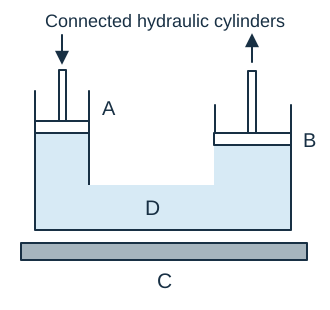
In the hydraulic arrangement, which labeled part carries the pressure increase from the small input piston to the large output piston?
Worked answer and explanation
Answer: D. D
D is the connected liquid beneath both pistons. A pressure change applied to the enclosed liquid is transmitted through it to the output piston. The frame supports the device, and the pistons apply and receive force.
Question 2: Support reactions
Question 2 · Support reactions · medium
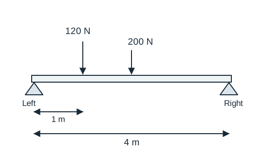
A uniform 4 m beam weighing 200 N rests horizontally on supports at its two ends. A 120 N load is placed as shown. The system is at rest. What upward force does the right support exert?
Worked answer and explanation
Answer: B. 130 N
Take moments about the left support. The beam’s 200 N weight acts at its midpoint, 2 m away, and the extra 120 N acts 1 m away. Thus the right reaction is (200 × 2 + 120 × 1) ÷ 4 = 130 N. Sharing the total weight equally would ignore the off-center load.
Question 3: Compound gear reduction
Question 3 · Compound gear reduction · medium
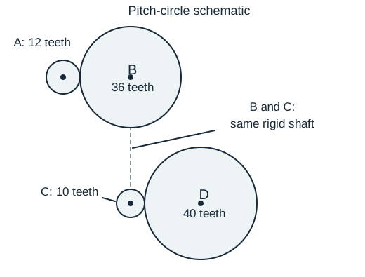
Gear A drives B. Gears B and C are rigidly fixed to the same shaft, and C drives D. The tooth counts are shown. If A turns at 720 rpm without slipping, how fast does D turn?
Worked answer and explanation
Answer: A. 60 rpm
The first pair reduces speed by 12/36, giving B and C 240 rpm. The second pair reduces that by 10/40, so D turns at 60 rpm. B and C share speed because they share a rigid shaft; their different tooth counts must not be treated as a third meshing pair.
Question 4: Restrained thermal stress
Question 4 · Restrained thermal stress · hard
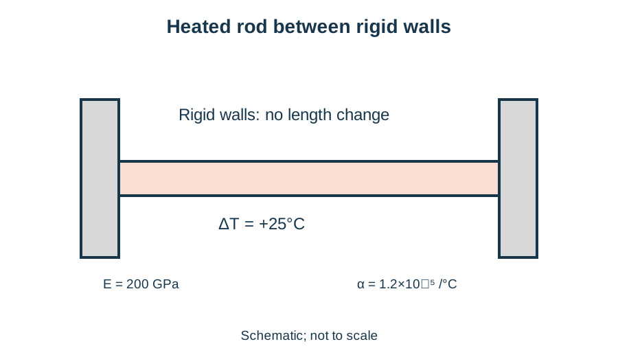
A straight rod is held between rigid walls so its overall length cannot change. Heating it by 25°C would make it expand freely. Use the ideal linear model σ = EαΔT, with E = 200 GPa and α = 1.2×10⁻⁵/°C. What is the magnitude and type of stress produced?
Worked answer and explanation
Answer: B. 60 MPa compressive
For a fully restrained warm rod, free thermal strain αΔT is prevented and becomes compressive stress. EαΔT = 200,000 MPa × 1.2×10⁻⁵/°C × 25°C = 60 MPa. The tensile choices have the wrong sign.
Question 5: Lever classes
Question 5 · Lever classes · easy
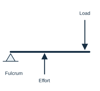
The lever’s fulcrum, effort, and load are located as shown. Which part is between the other two?
Worked answer and explanation
Answer: D. The effort
The effort acts between the fulcrum and the load. This is a third-class arrangement, which commonly trades increased effort for greater load travel or speed.
Question 6: Work from a force graph
Question 6 · Work from a force graph · medium
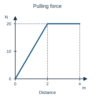
The graph shows the forward pulling force on a cart over 4 m. The force rises linearly from 0 to 20 N during the first 2 m, then stays at 20 N. A constant 5 N friction force opposes the cart throughout. What is the net work on the cart over these 4 m?
Worked answer and explanation
Answer: B. 40 J
The pull does the area under its graph: ½ × 2 × 20 + 2 × 20 = 60 J. Friction does −5 × 4 = −20 J. Net work is 40 J. The 60 J choice includes the pull but omits friction.
Question 7: Continuity of liquid flow
Question 7 · Continuity of liquid flow · medium
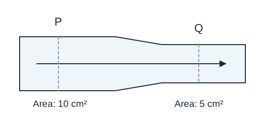
Water flows steadily through the full pipe shown. There are no leaks or branches, and water is treated as incompressible. If its average speed at section P is 20 cm/s, what is its average speed at Q?
Worked answer and explanation
Answer: D. 40 cm/s
The same volume per second passes both sections, so area × average speed is constant. The area falls from 10 to 5 cm², so speed doubles: 20 × 10 ÷ 5 = 40 cm/s. Halving speed would reduce the flow rate instead of preserving it.
Question 8: Sliding versus tipping
Question 8 · Sliding versus tipping · hard
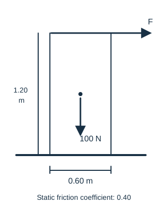
A uniform block weighs 100 N, has a 0.60 m-wide base, and is 1.20 m tall. A horizontal force at its top increases slowly as shown. The coefficient of static friction is 0.40. Which occurs first: sliding or tipping? Treat the floor and block as rigid.
Worked answer and explanation
Answer: B. Tipping begins at 25 N
Sliding would require 0.40 × 100 = 40 N. Tipping about the lower-right corner begins when F × 1.20 = 100 × 0.30, giving F = 25 N. Since 25 N is lower, tipping begins before the sliding threshold is reached.
Question 9: Rack-and-pinion motion
Question 9 · Rack-and-pinion motion · easy
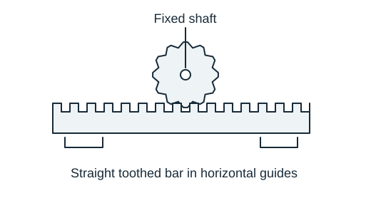
The round gear turns on a fixed shaft and meshes with the straight toothed bar shown. What motion can this arrangement directly produce in the bar?
Worked answer and explanation
Answer: C. Straight-line motion along the bar
The rotating pinion pushes successive teeth of the rack, translating the rack along its length. The straight bar does not rotate about the pinion shaft. This is a conversion between rotary and linear motion.
Question 10: Springs in series
Question 10 · Springs in series · medium
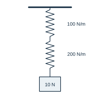
Two weightless springs are connected in series as shown. Their stiffnesses are 100 N/m and 200 N/m. A 10 N load hangs at rest. Both obey Hooke’s law. What is the total extension from their unloaded combined length?
Worked answer and explanation
Answer: D. 0.150 m
Each series spring carries the same 10 N tension. Their extensions are 10/100 = 0.10 m and 10/200 = 0.05 m, so the total is 0.15 m. Adding stiffnesses directly would describe a parallel arrangement, not this chain.
Question 11: Parallel springs
Question 11 · Parallel springs · medium
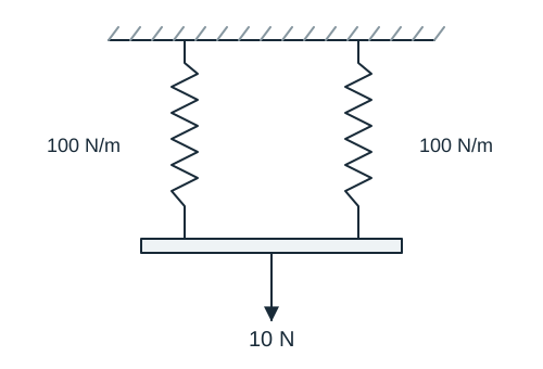
Two identical vertical springs support a weightless rigid bar as shown. A centered 10 N load keeps the bar horizontal. Each spring has stiffness 100 N/m and obeys Hooke’s law. Neglect spring weight and assume both were unstretched before loading. How far does the bar move downward?
Worked answer and explanation
Answer: B. 0.050 m
The identical springs extend equally and share the 10 N load, so each carries 5 N. Each extension is 5 ÷ 100 = 0.050 m, which is also the bar’s downward movement. Treating either spring as carrying all 10 N would double the result.
Question 12: Rotary brake energy and torque
Question 12 · Rotary brake energy and torque · hard
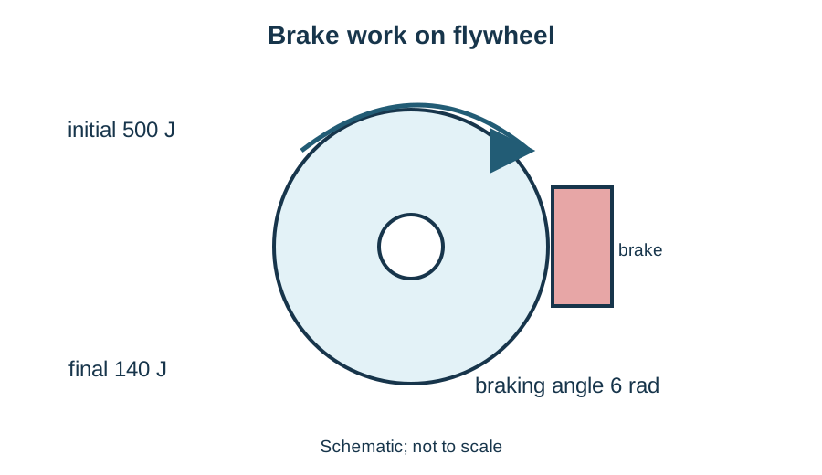
A flywheel’s rotational kinetic energy falls from 500 J to 140 J while a brake acts through 6 radians. Assume the resisting torque is constant and all lost kinetic energy becomes brake work. What is the torque magnitude?
Worked answer and explanation
Answer: C. 60 N·m
The brake removes 500 − 140 = 360 J. Constant torque does work τθ, so τ = 360 J/6 rad = 60 N·m. Using the final energy alone, adding energies, or ignoring angular displacement misstates the balance.
Before moving on, choose one error you can explain. Rework that question with the solution closed, then revisit the skill in a later session to check what you remember.
Common mistakes to check
Measuring lever arms from an endpoint instead of the pivot.
Assuming every pulley adds the same mechanical advantage.
Ignoring whether gears mesh or share a shaft.
Treating a larger output force as free energy without considering distance.
Mark the motion and constraints
Locate pivots, fixed supports, ropes, contact points and the moving load. Add an arrow for each known motion. Work outward one connection at a time rather than trying to judge the whole drawing at once.
State the model’s assumptions
A question may ignore friction, rope mass or energy losses to isolate a principle. Use the stated model. If you make a prediction such as “less force but more distance,” check that both parts agree with the diagram and the conservation of energy.
Test format and scoring reference
Mechanical Comprehension is not part of the AFQT. It contributes to relevant service job composites, where it measures knowledge of mechanical and physical principles alongside other subtests.
View Mechanical Comprehension questions and time limits
Mechanical Comprehension: official test format
Format
Questions and timing
Computer test, without tryouts
15 scored questions · 22 minutes without tryouts
Computer test, with tryouts
15 possible additional unscored questions · 42 minutes total with tryouts
Paper test
25 questions · 19 minutes
Domain
Science & Technical
Contributes to the AFQT
No
The computer test includes unscored tryout questions in selected subtests. The longer time shown is the total for a section with tryouts, not extra time to add. These figures describe the proctored CAT-ASVAB, not untimed PiCAT or our practice sets. See the official questions and timing table and the guide to test versions.
The official subtest concerns mechanical and physical principles. Common study areas include forces, motion, simple machines, pressure and basic energy relationships.
No. Mechanical Comprehension focuses on physical principles. Auto Information focuses on automobile systems and technology, although some underlying ideas overlap.
Identify which pulleys move with the load, trace the rope and count the segments supporting that moving assembly. Then apply the assumptions stated in the question.
No. They are original study questions. Official job eligibility depends on official scores and the service’s other requirements, not a result on this practice set.
Sources and materials. Subtest descriptions and timing were checked on September 29, 2026 against the Department of Defense’s What to Expect guide, sample questions and score guide. Teaching examples, diagrams and practice questions are independently authored Test Ninjas materials. Test Ninjas is not affiliated with or endorsed by the Department of Defense.