ASVAB Electronics Information: Trace the Circuit First
A circuit’s connections tell you which quantities are shared. Learn to trace those connections before using a formula, starting with a parallel circuit that makes the difference between voltage and current clear.
Test Ninjas Research · Updated September 29, 2026
What you’ll learn
Identify series and parallel connections from their paths.
Apply Ohm’s law with the correct quantity and unit.
Explain why branch currents can differ at the same voltage.
Learn the method
Find current in two parallel branches
An ideal 12-volt source connects across two parallel resistors, one 6 ohms and one 3 ohms. What current flows through each resistor? Ignore wire and source resistance.
Both branches span the same 12 V source. Each resistor has its own current path.
Find the shared connection points
Both resistors connect between the same top and bottom wires. Each branch therefore has the full 12-volt potential difference across it.
Calculate one branch at a time
Rearrange V = IR as I = V ÷ R. For the 6-ohm resistor, I = 12 ÷ 6 = 2 amperes. For the 3-ohm resistor, I = 12 ÷ 3 = 4 amperes.
Check the relationship
At the same voltage, the smaller resistance allows the larger current. The source supplies the sum of the branch currents: 2 + 4 = 6 amperes.
2 A through the 6 Ω resistor and 4 A through the 3 Ω resistor.
Why the tempting approach fails
Adding 6 Ω and 3 Ω to get 9 Ω would treat the resistors as a series connection. In this diagram, current has two paths; it does not pass through both resistors in sequence.
Explain it back
If the 3-ohm branch is opened, does the current in the 6-ohm branch change in this ideal model?
Compare your reasoning
No. The ideal source still places 12 V across the 6 Ω resistor, so its current stays 2 A. Total source current falls to 2 A because the other path is interrupted.
Key concepts to keep handy
The example teaches one method. Open a concept below when you need a rule or a different type of example during practice.
Know which quantity is being measured
Voltage is an electric potential difference, measured in volts. Current is the rate of charge flow, measured in amperes. Resistance opposes current and is measured in ohms. For a resistor modeled by Ohm’s law, V = IR. A 12-volt potential difference across a 4-ohm resistor produces a current of 3 amperes.
Trace the path through the circuit
A series circuit has one path through its components, so the same current passes through each. Parallel branches share the same voltage between their common connection points, while branch currents can differ. Follow wires and junctions rather than judging which components look close together on the page.
Distinguish an open circuit from a short
An open circuit interrupts a conducting path. An ideal short circuit provides a path with negligible resistance that may bypass another component. They are different changes: a break stops current along that path, while a short can greatly increase current. Interpret these as circuit models for the question.
Link components to what they do
A resistor limits current in a circuit, a capacitor stores energy in an electric field, and a diode conducts much more readily in one direction than the other. A switch opens or closes a path. Start with the function being asked about, then match the component or circuit symbol.
Topics covered in this guide
Voltage, current, resistance and their units
Ohm’s law and electrical power
Series and parallel circuits
Conductors, insulators and switches
Resistors, capacitors, diodes and basic electrical components
Now apply what you know
Try a few questions without opening the solutions, then explain why each answer works. Use scratch paper for calculations and work without a calculator. These original, untimed questions sample the subject; the result is not an official score.
Electronics Information practice: 12 questions
Work through one question at a time. Explain your approach, check the worked answer, then move on. Use scratch paper for calculations.
0 of 12 checked · 0 correct.
Progress is saved in this browser. These original study questions do not produce an official AFQT score.
Question 1: Circuit-symbol recognition
Question 1 · Circuit-symbol recognition · easy
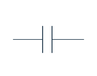
Which component is represented by the symbol shown?
Worked answer and explanation
Answer: C. A capacitor
Two separated parallel plates represent a capacitor. An inductor uses a coil symbol, and a transformer includes two coupled coils rather than this single pair of plates.
Question 2: Polarity in a waveform
Question 2 · Polarity in a waveform · medium
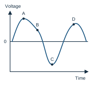
The graph shows voltage at terminal P relative to terminal Q. At which labeled time is P negative relative to Q?
Worked answer and explanation
Answer: C. C
Only the point marked C lies below the zero-voltage axis. Negative relative voltage means P is at a lower potential than Q at that instant; points above zero have the opposite polarity.
Question 3: Bypassed resistors
Question 3 · Bypassed resistors · medium
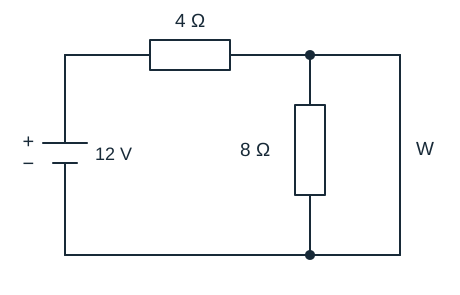
All wires in this model have zero resistance. With wire W connected as shown, what current flows through the 8 Ω resistor?
Worked answer and explanation
Answer: A. 0 A
Wire W directly joins the two terminals of the 8 Ω resistor, making their potential difference zero. Its current is therefore 0 ÷ 8 = 0 A. The supply still sends 12 ÷ 4 = 3 A through the 4 Ω resistor and the bypass wire.
Question 4: Power in a compound network
Question 4 · Power in a compound network · hard
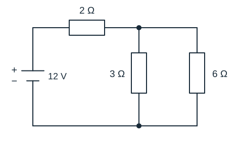
In the ideal circuit shown, how much power is dissipated by the 6 Ω resistor?
Worked answer and explanation
Answer: B. 6 W
The parallel combination is (3 × 6) ÷ (3 + 6) = 2 Ω. With the series 2 Ω resistor, total resistance is 4 Ω and source current is 3 A. The parallel section therefore has 6 V across it, so the 6 Ω resistor dissipates 6² ÷ 6 = 6 W. Using the full 12 V across that branch would incorrectly give 24 W.
Question 5: Identifying a series pair
Question 5 · Identifying a series pair · easy
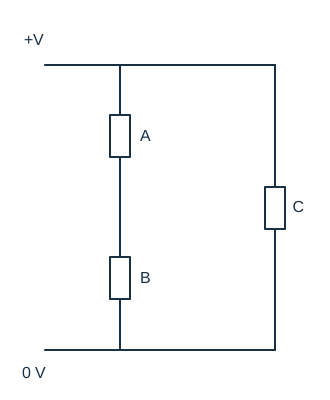
Which two labeled resistors form a series pair, with no branch connection between them?
Worked answer and explanation
Answer: A. A and B
A and B share a junction with no branching path, so the same branch current passes through both. C is in a separate branch across the supply and does not form a series pair with either one individually.
Question 6: Parallel switch paths
Question 6 · Parallel switch paths · medium
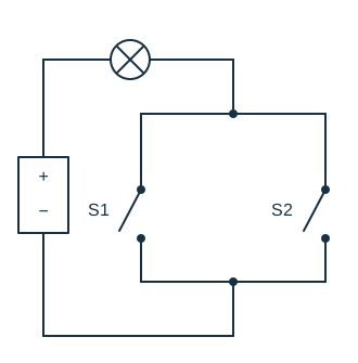
In this ideal circuit, the lamp lights whenever a complete path through it connects the supply terminals. Which statement describes all the switch settings that light the lamp?
Worked answer and explanation
Answer: B. Either switch may be closed, or both may be closed
S1 and S2 form alternative parallel paths. Closing S1 completes one path through the lamp even with S2 open. Opening both breaks every available path.
Question 7: Lenz’s law for a retreating magnet
Question 7 · Lenz’s law for a retreating magnet · medium
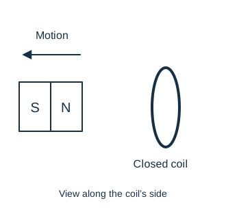
The north pole of the bar magnet faces a closed conducting coil. The magnet moves away from the coil as shown. According to Lenz’s law, what magnetic pole develops on the coil face nearest the magnet, and what effect does it have?
Worked answer and explanation
Answer: A. South; it attracts the retreating north pole
The induced field opposes the change caused by the magnet moving away. The near coil face becomes south, attracting the retreating north pole and opposing separation. Lenz’s law opposes the change in magnetic flux, not every existing field.
Question 8: Oscilloscope input termination loads a signal
Question 8 · Oscilloscope input termination loads a signal · hard
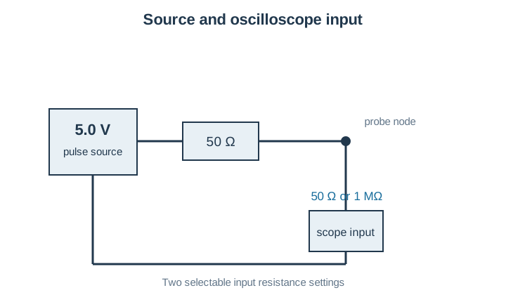
In the diagram, an ideal 5.0 V pulse source has a 50 Ω SERIES output resistor. The scope input can be set to 50 Ω or 1 MΩ. At a slow flat portion of the pulse, what should the scope display with the 50 Ω setting, and why does it differ from the nearly 5 V high-impedance reading?
Worked answer and explanation
Answer: B. About 2.5 V because the output and input resistances form equal halves of a divider
The two 50 Ω resistances divide the ideal 5.0 V pulse equally: Vinput=5×50/(50+50)=2.5 V. A 1 MΩ input draws little current, leaving nearly the full 5 V. A 50 Ω input is a finite load, not a zero-ohm short.
Question 9: Earth-connection symbol
Question 9 · Earth-connection symbol · easy
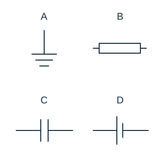
Which labeled symbol represents an earth connection?
Worked answer and explanation
Answer: A. A
A shows the conventional earth symbol, with a vertical connection and successively shorter horizontal bars. B is a resistor, C a capacitor, and D a cell. These symbols describe different circuit functions.
Question 10: Junction currents
Question 10 · Junction currents · medium
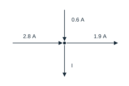
The arrows show steady currents at one junction. What is the current I in the direction shown?
Worked answer and explanation
Answer: C. 1.5 A
The incoming currents total 2.8 + 0.6 = 3.4 A. The outgoing currents must have the same total, so I = 3.4 − 1.9 = 1.5 A. Adding every labeled current ignores the directions of flow.
Question 11: Diode bias
Question 11 · Diode bias · medium
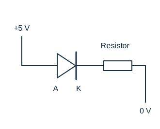
For the ordinary diode shown, the anode connects to +5 V and the cathode connects through a current-limiting resistor to 0 V. Which description applies?
Worked answer and explanation
Answer: C. It is forward biased
A diode is forward biased when its anode is sufficiently positive relative to its cathode. Here the stated polarity is forward; the resistor limits current rather than reversing the diode’s bias.
Question 12: Primary current of a loaded ideal transformer
Question 12 · Primary current of a loaded ideal transformer · hard
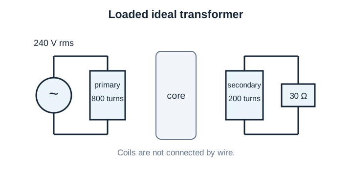
For the ideal transformer shown, the 240 V rms primary has 800 turns. The 200-turn secondary feeds only the shown 30 Ω resistor. What is the primary rms current?
Worked answer and explanation
Answer: C. 0.5 A
The turns ratio makes secondary voltage 240 × 200/800 = 60 V rms. The 30 Ω load draws 60/30 = 2 A, so output power is 120 W. In an ideal transformer input power is also 120 W; primary current is 120/240 = 0.5 A. The 2 A choice is secondary current.
Before moving on, choose one error you can explain. Rework that question with the solution closed, then revisit the skill in a later session to check what you remember.
Common mistakes to check
Swapping volts, amperes and ohms in a calculation.
Assuming current is the same in every parallel branch.
Treating every crossing line as an electrical junction without checking the diagram.
Confusing a broken path with a low-resistance bypass.
Annotate before calculating
Label the source, the component being asked about and the known units. Rearrange V = IR to isolate the requested quantity before substituting values. For power, P = VI relates watts, volts and amperes; do not confuse power with energy used over time.
Explain circuit changes in words
Before calculating, predict what happens when resistance rises at a fixed voltage, or when a switch opens a particular branch. Then use the formula or diagram to check the prediction. This exposes an incorrect circuit interpretation early.
Test format and scoring reference
Electronics Information does not enter the AFQT. It can contribute to service composites used for technical job qualification. Meeting a composite threshold is only one part of a job’s eligibility requirements.
View Electronics Information questions and time limits
Electronics Information: official test format
Format
Questions and timing
Computer test, without tryouts
15 scored questions · 10 minutes without tryouts
Computer test, with tryouts
15 possible additional unscored questions · 21 minutes total with tryouts
Paper test
20 questions · 9 minutes
Domain
Science & Technical
Contributes to the AFQT
No
The computer test includes unscored tryout questions in selected subtests. The longer time shown is the total for a section with tryouts, not extra time to add. These figures describe the proctored CAT-ASVAB, not untimed PiCAT or our practice sets. See the official questions and timing table and the guide to test versions.
No. It is a separate technical subtest that contributes to relevant service job composites rather than the AFQT.
Start with Ohm’s law, V = IR, and power, P = VI. Learn the quantities, units and assumptions as well as the equations, then practice rearranging them.
Follow the connections. Series components lie on a single current path; parallel branches connect between the same two nodes. The drawing’s physical layout alone does not determine the connection.
No. The practice is based on diagrams and conceptual calculations. Its examples are study models, not instructions for working on live electrical equipment.
Sources and materials. Subtest descriptions and timing were checked on September 29, 2026 against the Department of Defense’s What to Expect guide, sample questions and score guide. Teaching examples, diagrams and practice questions are independently authored Test Ninjas materials. Test Ninjas is not affiliated with or endorsed by the Department of Defense.